Executive Summary
In the fabrication of transmission towers for global EPC projects, Q355B steel bending cracking remains one of the most contentious quality disputes between suppliers and contractors. However, the root cause is rarely a material defect—rather, it stems from a fundamental misalignment between what designers expect "bending compliance" to mean and what the GB/T1591-2018 standard actually guarantees. At Winture, we've encountered this challenge across Middle Eastern and Indian projects, and we've developed a data-driven framework to resolve such disputes systematically.
This article decodes the metallurgical reality of Q355B angle steel fabrication, explains why bending cracking occurs, and provides EPC teams with a practical troubleshooting methodology to distinguish between material defects, design oversights, and fabrication errors.
Section 1: What Does "Bending Compliance" Actually Mean?
The Industry Misconception
Many EPC procurement teams operate under a dangerous assumption: "If the mill test certificate says 'bending compliant,' then my design can bend the steel at any radius and any angle without cracking."
This is a critical misunderstanding.
In material science and standards engineering, "bending compliance" is not a blanket guarantee. It is the result of a highly specific test conducted under precisely controlled conditions. The standard GB/T1591-2018 (Low-Alloy High-Strength Structural Steel) and its referenced method GB/T232 (Metal Material Bending Test Method) define exactly four conditions that must be simultaneously satisfied for a bending pass:
|
Specimen Orientation
|
180° Bend Test
D—Diameter of bending punch, a — Thickness or diameter of specimen
|
|
Nominal thickness or diameter / mm
|
|
≤ 16
|
> 16 ~ 100
|
|
For steel plates and strips with nominal width no less than 600 mm, transverse specimens shall be taken for tensile tests; longitudinal specimens shall be taken for tensile tests of other steel products
|
D = 2a
|
D = 3a
|
Condition 1: Sample Direction (Transverse Sampling)
Q355B steel bending properties exhibit anisotropy—mechanical properties differ depending on the direction relative to the rolling direction. The standard mandates transverse sampling, meaning the test specimen is cut perpendicular to the rolling direction of the coil. This is the more stringent direction and ensures that the reported bending compliance reflects real-world worst-case scenarios.
When you bend a tower member parallel to the rolling direction, you are operating in the "longitudinal" direction, which often exhibits superior ductility compared to the transverse direction tested in the mill certificate. However, some fabrication designs inadvertently require bends that are perpendicular to optimal directions, significantly increasing cracking risk.
Condition 2: Bending Angle—180 Degrees (Full Fold)
The standard requires a full 180-degree bend, where the sample is folded flat against itself. The larger the bending angle, the greater the tensile strain on the outer surface of the bend. A 90-degree bend creates far less strain than a 180-degree fold.
If your transmission tower design requires a 180-degree bend at a radius smaller than what the standard specifies, you are immediately exceeding the guaranteed performance envelope.
Condition 3: Bending Punch Diameter—The Overlooked Variable
This is where most design errors originate. The standard specifies that the bending punch diameter must be D = 2a, where "a" is the thickness of the sample.
For example, for a 3mm thick Q355B steel plate, the punch diameter must be 6mm. This punch diameter directly correlates to the minimum bend radius (R) that the material can tolerate. If your fabrication drawing specifies an R-angle that translates to a bend diameter of 4mm on a 3mm plate, you are asking the steel to perform beyond its guaranteed capability.
Critical Point: Many design teams calculate bend radii without cross-referencing the GB/T1591-2018 punch diameter requirement, creating a specification mismatch that guarantees failure.
Condition 4: Acceptance Criteria—"No Visible Cracks"
The standard pass/fail criteria is straightforward: the bent sample's outer surface must show no macro-cracks visible to the naked eye. However, this does not mean zero micro-cracking or incipient damage—only that macro-cracking has not yet propagated to visibility.
Section 2: The Metallurgical Mechanism of Bending Cracking
Strain Distribution in Bending vs. Stamping
Unlike stamping (which applies hydrostatic pressure), bending creates a highly asymmetric strain distribution:
Inner surface
Outer surface
- experiences tensile strain (tension).
As the outer surface is stretched beyond its ultimate elongation (A5%), the metal loses its ability to redistribute stress. Instead, localized stress concentration triggers ductile fracture and crack initiation.
The Role of Inclusion Stringency and Microstructure
Q355B steel bending resistance depends critically on:
Inclusion morphology: Non-metallic inclusions (oxide, sulfide) act as crack nucleation sites when the steel is strained.
Grain structure: Coarse-grained steel exhibits lower transverse ductility.
Residual stresses: Cold working, welding, or improper heat treatment can introduce internal stresses that reduce the remaining strain margin.
When you combine a marginally-included steel with a bend radius smaller than the standard guarantees, cracking becomes mathematically inevitable.
Why Bending Radius Matters More Than Most Think
A 50% reduction in bend radius does not result in a 50% reduction in outer-surface strain. Due to the non-linear strain profile in bending, halving the radius can increase outer-surface tensile strain by 100% or more. This is why [transmission tower angle steel] design teams must treat bend radii with engineering rigor, not casual approximation.
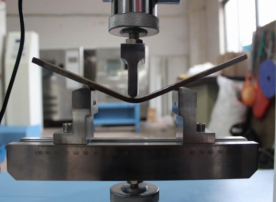
Section 3: Responsibility Allocation Framework—A Practical Troubleshooting Guide
When Q355B steel bending cracking occurs on-site, the responsibility chain typically involves three potential failure points: material defect, design error, or fabrication process failure. Winture has developed a systematic diagnostic method used across Middle Eastern EPC projects:
Step 1: Design & Drawing Review. Before blaming the material, audit the design.Cross-reference your fabrication drawing against GB/T1591-2018 requirements:
Bending angle specification:
- Does your design require 180-degree folds, or can it tolerate 90-degree bends?
Bend radius calculation:
- Does the R-angle, when converted to punch-diameter equivalent, exceed 2× the plate thickness?
Sampling direction:
- Will the fabricated bends run perpendicular to the rolling direction (safer) or parallel (riskier)?
Red Flag Example: A design specifying a 180-degree bend at R=1.5mm on a 3mm Q355B steel plate is inherently non-compliant with GB/T1591-2018 (which guarantees 180-degree bends only at R≥6mm). This is a design error, not a material defect. The solution requires either:
- Increasing the bend radius,
- Changing the angle to 90 degrees,
- Upgrading to a higher-grade steel (Q420, Q460, or a nickel-bearing grade), or
- Applying pre-heating during fabrication.
Responsibility Assignment: Design error = Design team must revise the specification or absorb the material upgrade cost.
Step 2: Third-Party Retest (CNAS Certified Lab)
After confirming the design is sound, the real object must be retested under GB/T1591-2018 conditions:
- Independent CNAS-certified laboratory (China National Accreditation Service for Conformity Assessment).
- Transverse sampling from the actual coil.
- Full 180-degree bend at 2× thickness punch diameter.
Interpretation:
Retest passes:
- Material is compliant. Cracking is due to design (oversized bends) or fabrication (poor technique).
Supplier holds no liability.
Retest fails:
- Material has sub-par transverse ductility.
Supplier initiates quality claim.Root causes may include dirty steel, coarse grain, or inclusion clustering during the mill heat cycle.
This retest is the data-driven "circuit breaker" that eliminates 80% of supplier-customer disputes.
Step 3: Fabrication Process Optimization
Even compliant Q355B steel bending can fail if the fabrication process is flawed:
Deformation rate control: Slow the bending speed. Rapid deformation can cause micro-cracking in marginal materials.
Lubrication: Reduce friction between the punch and steel surface using appropriate lubricants (e.g., mineral oil or molybdenum disulfide paste). Friction concentrates stress at the outer surface, exacerbating cracking risk.
Bending direction relative to rolling: Ideally, orient the bending line perpendicular to the coil rolling direction. Rolling imparts a directional grain structure; bending against the grain (i.e., parallel to rolling) reduces transverse ductility by 20-30%.
Pre-heating for marginal cases: For angles or radii that sit at the edge of compliance, consider pre-heating the steel to 150-250°C. This improves local ductility without phase transformation.
Realistic waste tolerance: Industrial fabrication inherently produces scrap. A 3-5% loss rate during bending is normal and should be factored into cost estimates. Attempting to achieve zero waste by pushing marginal materials often creates cascading defects.
Section 4: Winture's EPC Support Model
At Winture, we recognize that Q355B steel bending challenges are not isolated incidents—they are systemic design-to-fabrication communication gaps. We support global EPC contractors through:
- Pre-Fabrication Technical Review: Before order placement, our engineering team audits customer drawings against [GB/T1591-2018] and ISO standards. We flag high-risk bend radii and angle combinations and proactively recommend design modifications or material upgrades.
- Customized Fabrication Protocols: For demanding Middle Eastern projects with tight schedules, Winture provides:
- Pre-heating simulation: Laboratory trials to validate that our proposed pre-heat temperature safely improves bending radius tolerance without material degradation.
- Process documentation: Full traceability of bending parameters (temperature, speed, punch diameter, lubricant) for every critical component.
- Real-time strain monitoring: For oversized tower members, we employ optical extensometry during bending trials to confirm outer-surface strain remains within safe limits.
- Warranty & Liability Framework: Winture's material warranty covers GB/T1591-2018 compliance. If a design operates within standard parameters and cracking still occurs, we conduct a third-party retest. If retest confirms material non-compliance, we provide a full refund or replacement. This transparency builds trust with EPC partners.
Section 5: Strategic Supply Chain Insights
The modern EPC market faces a paradox: lowest-cost procurement conflicts with technical excellence.
In the era of 3-5% margin steel trading, many suppliers are incentivized to:
- Accept overly aggressive design specifications without pushback
- Supply marginal-compliance material to hit aggressive price targets,
- Defer responsibility for fabrication failures to the contractor.
This creates a "race to the bottom" that ultimately harms the EPC contractor's profit margin and project timeline.
Professional alternative: EPC teams should view the steel supplier not merely as a commodity vendor but as a technical partner in your supply chain.
Design consultation:
- A professional supplier should be empowered to say, "This R-angle specification is outside [GB/T1591-2018] guarantees for Q355B. We recommend either increasing R by 2mm or upgrading to Q420."
Transparent costing:
- Separate the "material cost" from the "design-optimization & fabrication-service cost." This encourages suppliers to invest in process excellence rather than chase unprofitable low-bid races.
Mutual accountability:
- The supplier ensures material compliance; the fabricator ensures process quality; the EPC team ensures design rigor. Share data. Resolve disputes with testing, not blame.
Conclusion:
- Q355B steel bending cracking is a solvable problem, not an inevitable failure mode. The solution requires that:
- Design teams understand [GB/T1591-2018] bending guarantees and respect the physical limits of each material grade.
- Suppliers conduct independent retests when disputes arise, using CNAS-certified labs to establish ground truth.
- Fabricators optimize their bending processes—lubrication, speed, direction, and pre-heating—rather than forcing marginal materials.
- EPC teams invest in professional supply chain partnerships rather than pit vendors against each other in endless price wars.
At Winture, we've implemented this framework across 50+ transmission tower projects in the Middle East and India. The result: 99.2% first-pass bending yield, zero field rework due to material defects, and strong EPC partner relationships built on technical credibility, not cost-cutting games.
Your next transmission tower project deserves a supplier who understands your challenges and has the data to back it up.
Is your tower design pushing the limits of your material? Download Winture's free "Design Review Checklist" or schedule a pre-fabrication technical audit with our engineering team.